White W.B. and White E.L.
Abstract: Development of large collapse structures in karstic terrain requires an interaction between mechanical instability and chemical removal of collapsed rock. Upward migration of pre-existing voids can choke out if there is no mechanism for the efficient removal of fallen blocks. Rates of dissolution, size of initial cavity, and overlying bedrock characteristics determine the size of the final surface landform. Collapse features range in scale from small sinkholes to hundreds of meters in such features as the Golondrinas collapse pit in Mexico. Tiankengs are interpreted as end members features on a continuous scale.
Keywords: Development, large collapse, structures, karstic terrain, interaction, mechanical instability, chemical removal, collapsed rock, Upward migration, pre-existing, voids, choke out, mechanism, efficient removal, fallen blocks, Rates of dissolution, initial cavity, overlying, bedrock, characteristics, surface landform, Collapse, sinkholes, Golondrinas, Mexico, Tiankengs
Introduction
Tiankengs, or giant dolines, are closed depressions formed mainly by mechanical collapse of limestone beds coupled with dissolutional removal of collapsed blocks. Collapse plays an important role in most karst processes but is generally considered to be secondary to dissolutional processes. The objective in the present paper is to compare collapse and dissolutional processes and the way in which the resulting landforms scale with size. Ultimately, it is shown how tiankeng fit into the family of closed depression landforms. The problem is approached by taking a very broad look at closed depression features of all types and gradually focusing in on the specific features of interest.
Closed depression landforms
Scaling Parameters
To describe closed depression landforms, the only basic measurement needed is a length scale. The physical dimensions of closed depressions, depth and width, are the most commonly used. The width scale length varies over about four orders of magnitude. The smallest depressions that can be recognized as distinct karst features have dimensions of about one metre. The largest are the Dinaric poljes with dimensions of tens of kilometres. The range of the depth scale is about three orders of magnitude. There are recognizable depressions with depths of less than one metre. The maximum depths are less than 1000 m (excluding entire cave systems, where the accumulated depth may exceed 2000 m).
The area of closed depressions has been used as a scaling parameter. Various definitions of area have been proposed. Area can be defined as the area lying within the highest closed contour on a map of the depression feature. As recharge inputs to karst aquifers, the entire catchment draining into the closed depression is a useful concept (White and White, 1979). Drainage divides can be mapped between closely spaced depressions in polygonal karst (Williams, 1972). Volume would also be useful, but volume is less easily extracted from maps and other data sources. In the present discussion, only length measurements are considered.
To further differentiate between categories of landforms, it is helpful to define various dimensionless aspect ratios. Most closed depressions have length/width ratios on the order of unity although some are elongate. Very high values would describe solutionally widened fractures of various sorts. These are not considered in this discussion. The depth/width ratio is the most useful. Depressions with depth/width ratios in the range of unity or less are usually classified as dolines (or the roughly equivalent term sinkhole, that is widely used in the United States, especially in the hydrogeological and engineering literature). Features with depth/width ratios much greater than unity are considered to be pits or shafts.
For the present discussion, a third aspect ratio is needed, the ratio of the diameter at the top of the depression to the diameter at the bottom of the depression (Fig. 1). The usual dolines are bowl-shaped – wide at the top and narrow at the bottom. Many pits and shafts maintain a more or less uniform width from top to bottom. However, depressions formed by collapse of underlying cave chambers tend to bell out with depth so that the bottom is wider than the top. There is also a reversal of curvature. Dolines tend to be concave upward; collapse chamber structures tend to be concave downward.
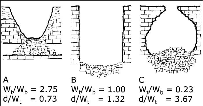
Fig. 1. Sketch showing top width/bottom width aspect ratios, Wt/Wb, and depth/width ratios, d/Wt, for closed depression features resulting primarily from collapse. (A) Collapse doline; weathering and slumping of walls and later soil mantling produces a bowl-shaped profile often indistinguishable from a solution doline. (B) Vertical walled doline or stoping shaft: stable wall rock and vertical fractures preserve the vertical profile. (C) Breakout dome that has intersected the land surface: internal profile reflects the original stress arch.
Processes
Closed depressions result from the operation of some combination of three processes: dissolution of the bedrock, collapse of underlying cavities, and the piping or suffosion of unconsolidated soils. The latter is the most important process from the viewpoint of land use hazards. When the engineering literature or the popular press speaks of sinkholes, they are usually referring to soil piping and suffosional features. For present discussion, we are concerned only with the dissolution and mechanical collapse processes.
The processes at work in the development of large closed depressions are:
- Dissolution by vertically-moving water
- Mechanical stoping.
- Dissolution by horizontally moving water.
- Horizontal mechanical transport, mainly by flood waters.
Chemically undersaturated water moving vertically along fractures, and especially along fracture intersections, can enlarge them into a variety of chimneys, pits and shafts. Where the active agent is a fast-moving film of water clinging to the walls, the result is a shaft with near-vertical walls, including the vertical shafts of eastern United States (Pohl, 1955; Brucker et al., 1972). Large volumes of rapidly moving water introduce splashing and mechanical erosion to produce the more rugged and irregular vertical features such as, for example, the deep shafts of alpine caves in Europe or those found in the high plateaus of Mexico.
Mechanical stoping is the result of mechanical failure of the ceiling of pre-existing cavities. The intrinsic mechanical strength of overlying beds and the existence of fractures are the main parameters. Because stoping depends on mechanical properties of the rock and not chemical properties, a stoping shaft initiated in a cavity in soluble rock can extend upward into non-soluble rocks. An example is Dante’s Descent in the Coconino Plateau, Arizona, USA, where an initial cavity of the Mississippian Redwall Limestone has migrated upward through layers of sandstone and lava flows to produce a shaft 100 m deep and open at the surface (Fig. 2). Another example is the Big Hole, near Braidwood, NSW, Australia (Jennings, 1966) where the upward stoping was through layers of sandstone.
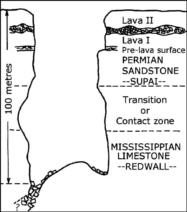
Fig. 2. Dante’s Descent, a stoping shaft that breaches non-carbonate strata.
Vertical mass movement, whether in solution or by stoping, is not sufficient for the development of closed depression features. There must also be lateral transport to carry the removed material away – ultimately to deposit it in a surface stream. For the dissolved load, transport is by flow in conduits draining toward springs. Mechanically stoped blocks that fall into an active stream are eventually dissolved and carried away in solution. However, insoluble materials can also be carried horizontally if there is sufficient stream power in the horizontally moving water. Flood flow is especially important.
If there is an initial cavity of volume VC, falling blocks due to stoping will fill the cavity and the void will migrate upward (Fig. 3). However, the bulk density of the accumulating rubble pile will be less than that of the original solid bedrock, so the void space will become smaller as it migrates upward. If there is no removal of the rubble at the base, simple mass balance arguments show that the volume of the shaft, VS, is

Here θ is the bulk porosity of the rubble pile. Depending on the volume of the original cavity and its depth below the surface, there may be a residual shaft that reaches the surface, or the incipient shaft may choke and fill before it reaches the surface. This process is identical to that of mine subsidence which produces anthropogenic sinkholes entirely in clastic rocks. If there is continuous and effective horizontal transport, there is no limit to how far the stoping shaft can migrate.
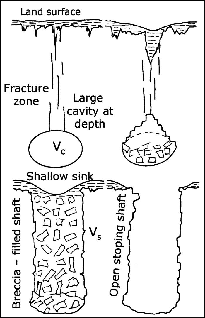
Fig. 3. Sketch showing the development of a stoping shaft with and without removal of accumulated rubble.
Dissolution and collapse are not mutually exclusive processes. Most closed depression features are the result of both. It is possible to separate features based on the dominance of one process over the other (Fig. 4).
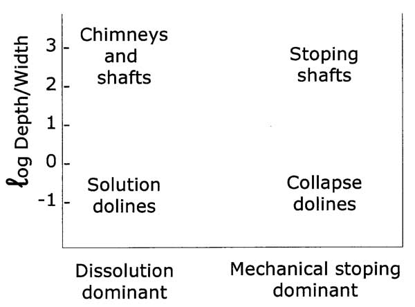
Fig. 4. Categories of closed depression features based on process. Only the depth/width aspect ratio is used but a size scale, perpendicular to the axes, would be needed to complete the figure.
Geological constraints
Processes that produce closed depression features by either chemical dissolution or by mechanical stoping must operate within constraints imposed by the geologic setting. Included among these constraints are:
- Thickness of carbonate rocks
- Depth to water table, commonly defined by regional base levels
- Large scale structure – folds and faults
- The fracture system
- Lithological characteristics of the carbonate rocks
The thickness of carbonate rock is a self-evident constraint on dissolution processes. Solution dolines and solution shafts will have their depths limited by the available thickness of soluble rock. Soluble rock thickness is less constraining on collapse dolines and stoping shafts which may migrate upward through non-carbonate rock.
Closed depression features are usually considered to be primarily phenomena of the vadose zone. With this constraint, deep air-filled depressions are only possible in regions with deep water tables, exactly the conditions at the sites of the Chinese tiankengs. The horizontal transport system at the base of large collapse structures may be a free surface stream, but it could also be a conduit in the phreatic zone. There exist water-filled closed depression features such as the cenotes of the Yucatan Peninsula in eastern Mexico, which may have originated as vadose zone features, before being flooded by post-Pleistocene sea level rise. An exceptional feature is Zacatón in Tamaulipas, Mexico (Gary, 2002). This is a shaft, 350 m deep and around l00 m across, comparable in size to the tiankeng, but entirely water-filled.
Large scale structures, mainly folds and faults, create the setting in which karst development can take place. Very deep shafts can develop in relatively thin limestones if the limestone beds happen to be nearly vertical. For the interpretation of specific features, the local fracture system and the details of bed thickness and bed lithology are the most important geological parameters.
The entries on the list of geological constraints are, in effect, independent variables. To produce extremely large and optimally developed features of any category, all of the variables must be optimized. The tiankengs, as giant collapse structures, have developed under near optimum conditions. Limit some of these conditions, especially thickness of carbonate rock and depth to base level, and there appear features with most of the characteristics of the tiankeng, but on a very small scale. The feature shown in Figure 5 is a common collapse doline, also known as a karst window. Vertical fracturing has produced the vertical walls. There is a competent underground stream to dissolve away the collapse blocks, but the feature is on a size scale of 10 m instead of hundreds of metres.
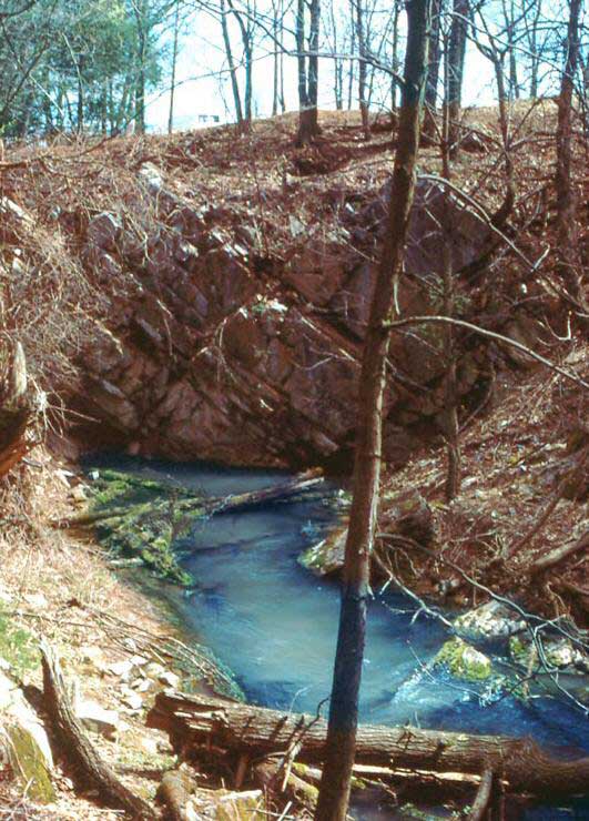
Fig. 5. Smullton Sink, Centre County, Pennsylvania, USA, a typical collapse doline.
Mechanical instability and stoping mechanisms
The breakdown process
The term breakdown is often used for both a material and a process. Breakdown, the material, consists of piles of rock fragments found in caves and at the base of closed depressions resulting from the mechanical failure of the roof. Breakdown, the process, is the assortment of mechanical, geologic, and hydrologic processes that can lead to roof failure. The mechanical analysis of roof stability is generally based on brittle fracture of fixed or cantilever beams (White and White, 1969; 2000). Account can also be taken of inelastic creep caused by microfracturing within the beds (Tharp, 1994). For the most part, a cave ceiling is either stable or it isn’t. Any beds with a thickness less than the critical value for a particular passage width will fall soon after the cave is drained. The ongoing breakdown process requires some mechanism by which a stable ceiling becomes unstable. Such mechanisms include dissolutional widening of ceiling fractures so that fixed beams are converted into cantilever beams, dissolutional removal of previously existing breakdown that may be propping up the ceiling, and any further widening of the passage. Further details of the geologic mechanisms triggering breakdown are given by Waltham (2002) and Osborne (2002).
Role of fractures and bed thickness
Roof collapse in thin-bedded limestones tends to be bed-by-bed. A stress arch develops over the cavity. If bed thicknesses are less than the critical thickness required by the width of the cavity, beds will fracture and collapse. If the overlying limestone strata are sufficiently thick, the beds will fail with each succeeding bed extending farther inward than the bed immediately below it. By this means, the collapse migrates upward until the process terminates at the stress arch. The end result is a dome-shaped chamber. If, however, the stress arch intersects the land surface, the breakdown dome will break through at the surface, producing an open pit which bells out the bottom (Fig. 1c). Breakdown chambers or breakout domes vary in size from a few metres to several hundred metres and are common in many caves.
There are two competing processes here, and the time relations between them are not always clear. The breakout dome is migrating upward by continuous spalling of the beds, while at the same time the overlying land surface is lowering by erosion and denudation. Although the evidence is not conclusive, it appears that most of the existing breakout domes reach a stable configuration quickly and early in the cave’s history. It is the lowering of the land surface that much later intersects the stress arch and thus triggers the final collapse that results in an open pit. Two examples from America are shown in Figure 6. Another would be the large chamber of Maoqi Dong, in the Leye karst, with its skylight hole on the ridge above.

Fig. 6. Profile maps of breakout domes that have intersected the land surface: Devil’s Sinkhole, Texas, USA (from Elliott and Veni, 1994), and Hellhole Cave, West Virginia, USA (from Dasher, 2001).
Regions with thickly bedded or poorly bedded limestones respond differently to stresses caused by the development of large cave passages. Massive limestones tend to be more stable and will support much larger cave passages. Breakdown, when it occurs, is more likely to be triggered by large vertical fractures rather than by separation along bedding plane partings. It is apparent that vertical fractures are a dominant controlling factor in the tiankeng. Figure 7 shows large vertical fractures in the wall of the Xiaozhai Tiankeng. Near-planar fracture surfaces can be seen in the walls of most tiankengs. It seems clear that tectonic processes that fracture the massive limestone beds are a major factor responsible for the occurrence of many tiankengs in southern China. Further evidence is provided by the karst towers, many of which also show extensive vertical fracturing (Fig. 8).
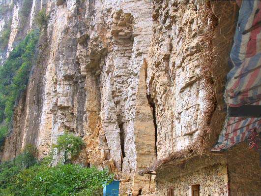
Fig. 7. Vertical fractures on the wall of Xiaozhai Tiankeng, Chongqing.
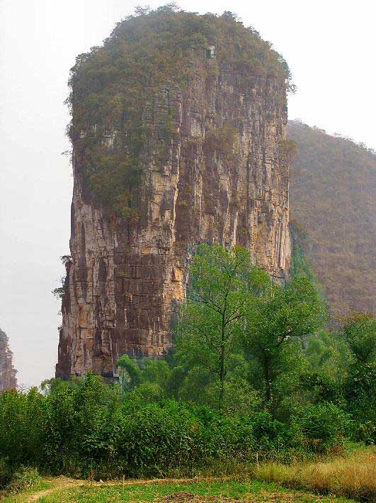
Fig. 8. Well-developed vertical fractures on a karst tower near Yangshuo, Guangxi.
Pre-existing cavities versus continuous lateral transport
Cave roof collapse is a dominant process in the final dying stages of a cave’s life cycle. As the land surface lowers, the epikarst punctures cave roofs, weakening beds, and initiating collapse. However, the truncation and decay phase of the cave life cycle can be stretched over hundreds of thousands of years. On a human time scale, cave roof collapses are rare although there are many cave passages that end in terminal breakdowns. Deep seated collapse in the absence of fracture control is even more rare. It seems unlikely that collapse alone could be responsible for large closed depression structures. Lateral transport is necessary.
Examples of large collapse structures
A question to be addressed is whether the Chinese tiankengs are unique karst features, in the sense that the conditions that formed them did not occur elsewhere in the world, or whether there are similar features elsewhere. If identical features do not exist, perhaps there are features that share a common theme with the tiankeng. Some possibilities are presented.
Icy Cove
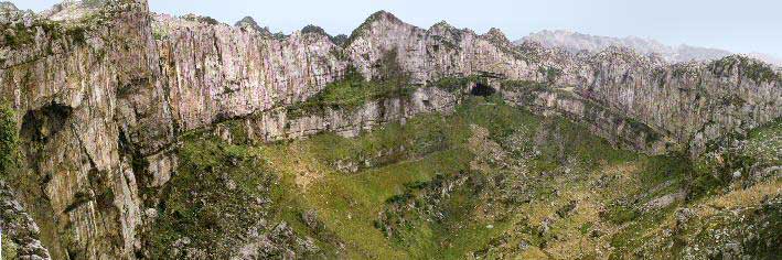
The largest solution/collapse structure in the Appalachian Mountains of eastern United States is Icy Cove, in the Cumberland Plateau of Tennessee. The Cumberland Plateau is capped with a massive conglomeratic sandstone of Pennsylvanian age. Underlying this, and cropping out on the valley walls, is a sequence of Mississippian limestones, with a total thickness of about 160 m. Icy Cove was initiated by deep dissolution in the limestone which then stoped upward, undermining the clastic rocks above. Collapse of the clastic beds produced a closed depression 150 m deep with a rim-to-rim diameter of one to two kilometres (Fig. 9). The depression is rimed with sandstone cliffs with steep lower slopes and a relatively flat floor.
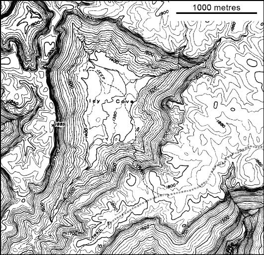
Fig. 9. Icy Cove, Cumberland Plateau, Tennessee, USA; contour interval is 20 feet (6 m) (map extracted from U.S. Geological Survey).
Tres Pueblos Sinkhole
The Rio Camuy rises on volcanic rocks in central Puerto Rico, flows northward, and then sinks at the contact with the Tertiary Lares Limestone. Underground, the river flows through the large gallery of the Rio Camuy Cave System (Gurnee and Gurnee, 1974). About half way between sink and resurgence is the Tres Pueblos Sinkhole, a collapse doline, 140 m in diameter and 120 m deep (Fig. 10). The river skirts the bottom of the doline. The Tres Pueblos doline would fit the classification of a normal tiankeng (Zhu & Chen, this volume). It is a collapse depression with near-vertical walls and with an active underground river to carry away fallen blocks.
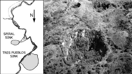
Fig. 10. The Tres Pueblos Sink, Rio Camuy Cave System, Puerto Rico (map from Gurnee, 1964; image from Monroe, 1976).
The Sótanos of Mexico
Zhu and Chen (this volume) note the sótanos of Mexico as possible tiankeng. Sótano means cellar or basement in Spanish but is also used as a general term for a pit by the local residents in the mountainous part of Mexico. There are three sótanos that have the 300 m depth comparable to a large tiankeng: Sótano de las Golondrinas, Hoya de las Guaguas, and one simply called El Sótano. There are many other pits on a smaller scale.
Sótano de las Golondrinas is the best known of the big Mexican pits (Raines, 1968; Sprouse and Fant, 2002). The entrance is on a hillside so the depth of the pit varies from 332 to 376 meters depending on the location of measurement. The pit is somewhat bottle-shaped (Fig. 11) with top dimensions of 49 x 62 m but with floor dimensions of 305 x 440 m. A narrow shaft near one wall can be descended for an additional 100 m, implying that the rubble pile occupying the floor is at least that thick.
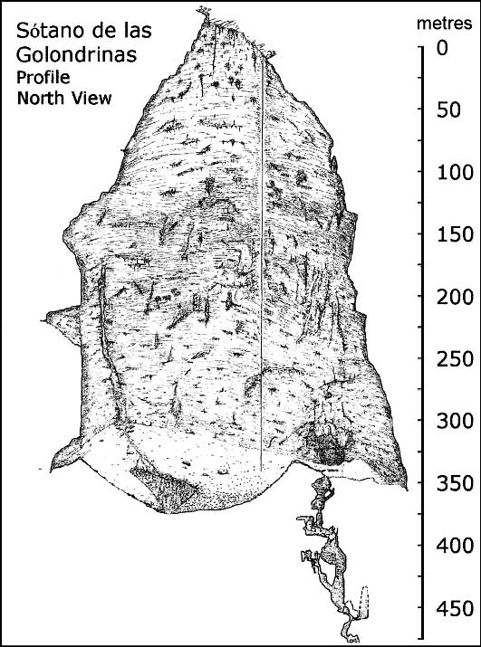
Fig. 11. Perspective profile of Sótano de las Golondrinas, San Luis Potosi, Mexico (from Sprouse and Fant, 2002).
Hoya de las Guaguas is an elongate pit developed along a major fracture (Fig. 12). It is in two sections. The open upper section is about 200 m deep, but then there is an offset, and the pit continues to a depth of 430 m. The pit walls bell out where they have expanded by serial breakdown through parallel fractures, but they are vertical at the ends of the main fracture. Hoya de las Guaguas may be an example of a major collapse structure in the making. If the off-set lower chamber were to stope its way to the surface, the result would be a large, deep, open pit with dimensions comparable to El Sótano.
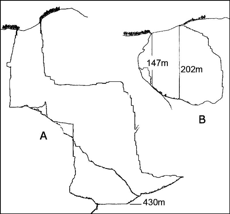
Fig. 12. Profiles of Hoya de las Guaguas, San Luis Potosi, Mexico. (A) is along the fracture direction. (B) is perpendicular to the fracture and shows only the upper half of the pit (adapted from Ralph, 1979).
El Sótano is a simple closed depression feature 440 m deep. It too is developed along a fault or major fracture so that the pit is elongate with the dominant fracture appearing on the map (Fig. 13). The walls are nearly vertical with a more gently sloping floor. Of all the Mexican pits, El Sótano may be closest to resembling the Chinese tiankeng.
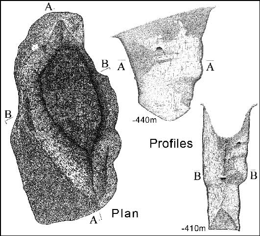
Fig. 13. Map and profiles of El Sótano, Mexico (from Bittinger, 1979).
There are many pits of various shapes and depths described in the literature on Mexico caves. What cannot be determined from published maps is the relative contribution of vertical dissolution and collapse. Data for five more of the largest pits have been added to data for the three above in Table 1. This entire set of eight closed depression features appear to be primarily collapse structures, whereas many of the other pits recorded in Mexico are primarily dissolution features. A common aspect of the chosen set of closed depressions is that none of them gives access to underground streams. However, by inference, the streams should either be somewhere deep below the bottom of the shaft, or at least have been there in the past, because otherwise it is difficult to account for the volume of material removed. In this sense the Mexican pits are immature, because the removal of the collapse rubble is incomplete. Likewise, each pit tends be formed on one major fracture (or fault), with less development of cross fractures. As a result, the pits tend to be elongate along the master fracture. These smaller pits have many of the morphological features of the tiankeng but do not meet the minimum size criteria.
The aspect ratios tabulated in Table 1 illustrate the difficulties in categorizing closed depression features. Dolines are usually taken as bowl-shaped (wider at the top than at the bottom) and relatively shallow (with depths comparable to or less than their widths). In terms of the aspect ratios, d/Wt should be ≤ 1. Closed depression features with d/Wt much greater than unity would be considered pits or shafts. None of the features in Table 1 has d/Wt less than unity, and many have values ranging up to 5. The Wt/Wb ratio gives a numerical measure of the overall profile of the closed depression (Fig. 1). With one exception, these ratios for the features listed in Table 1 are less than unity, meaning that these closed depressions bell out at the bottom and thus have shapes quite different from the usual dolines which would have Wt/Wb ratios substantially greater than unity.
Table 1.
Depth and aspect ratios for some large Mexican pits.
Scaling laws for closed depression features
The frequency of occurrence of closed depressions of any given depth falls off exponentially with depth. This has been demonstrated for a series of large populations of closed depressions (Fig. 14). All of the populations shown can be fitted to an equation of the form

In this equation, N is the number of dolines of any given depth, No is a fitting parameter, and K is a parameter with units of (metres)-1 characterizing the distribution. The Appalachian data set contains more than 5000 dolines including dolines in Mississippian limestone, in Ordovician limestone and in Ordovician dolomite. They all fit the same distribution function with the same numerical value of K, showing that the distribution of doline depths is relatively insensitive to carbonate rock lithology. However, different geographic settings, mainly a matter of local relief, produce different values of K. Lauritzen (2005) has introduced a half-depth defined as

and has developed a diffusion model for the continuing denudation of the karst surface. When he constructs a plot similar to Figure 14, but with depth normalized to the half-depth defined above, all distributions fall on the same straight line. Overall, these results show that closed depressions have a geometrical similarity that extends across both geology and distance scales.

Fig. 14. Distribution by depth of various populations of closed depressions (from Troester et al., 1984).
Although the data are much more sparse, closed depression diameters also appears to be distributed on a decaying exponential (White and White, 1987). The exponential distribution is not followed by all closed depressions. Impact craters, for example, are fractal and are distributed on a power law function rather than an exponential function.
We can now consider closed depression features with d/Wt ratios much greater than one. Again the data set is sparse. Troester et al. (1984) found an exponential distribution for pit depths in Alabama. Minton (2005) has tabulated the depths of the 50 deepest pits in Mexico. These range from 170 to 410 m and include the deep pits that are listed in Table 1. Those for which the pit is an entrance drop are plotted in Figure 15. There is considerable scatter because of the small data set but again the distribution is exponential. These data span the depth ranges of all but the largest of the Chinese tiankengs.
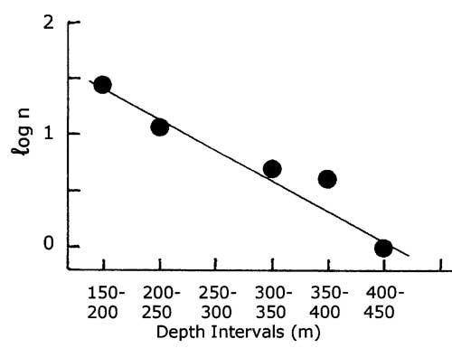
Fig. 15. Depth distribution of the deepest entrance pits in Mexico (data from Minton, 2005).
The tiankeng in the universe of closed depressions
Following the above rather convoluted discussion, an attempt can now be made to place the tiankeng into the overall scheme of closed depression features. From a geological point of view, tiankengs are vertical-walled collapse structures, closely associated with extensive vertical fracturing, and with a substantial cave river system required for lateral transport. From a consideration of the size distribution of closed depression features, tiankengs are not uniquely different from other collapse features, albeit at the extreme end of the size scale.
Leaving aside geology and looking only at geometry, the distinction between dolines and tiankeng is given by the aspect ratio Wt/Wb which should be in the range of unity. The exact numerical value at the boundary is not defined. Likewise, the aspect rate d/Wt distinguishes both dolines and tiankengs from pits and shafts, but the exact numerical value at the boundary is not defined. Finally, there must be a scale factor, of which the depth is a good candidate, that defines the minimum size for a feature to be considered a tiankeng. By these criteria, only a few of the Mexican closed depressions would be tiankengs. El Sótano certainly would be, and Sótano de las Guacamayos and Sótano de las Quilas could be. The others tend to bell out at the bottom, with Wt/Wb aspect ratios substantially less then unity. These pits, including Sótano de las Golondrinas would be immature tiankengs according to the given criteria. However, the bottle shape of Sótano de las Golondrinas is an end member of another group of features, the breakout chambers with skylights. There is not, in the karst geomorphological literature, a specific term for this latter shape of pit or closed depression.
Acknowledgements
We are immensely grateful to Professor Zhu Xuewen and his colleagues for arranging an outstanding opportunity to view the tiankeng landforms first hand. We thank the Chinese local officials for their excellent hospitality. Finally, we extend our appreciation to our colleagues on the investigating team for a very enjoyable excursion.
References
- Bittinger, C, 1979. The discovery of El Sotano. AMCS Activities Newsletter, 9, 80-83.
- Brucker, R W, Hess, J W and White W B, 1972. Role of vertical shafts in movement of ground water in carbonate aquifers. Ground Water, 10(6) 5-13.
- Dasher, G R, 2001. Hellhole. West Virginia Speleological Survey Bulletin, 15, 168-180.
- Elliott, W R, and Veni, G, 1994. The caves and karst of Texas. Guidebook for 1994 National Speleological Society Convention, [Huntsville, AL: National Speleological Society], 195.
- Gary, M, 2002. Understanding Zacatón: exploration and initial interpretation of the worlds deepest known phreatic sinkhole and related karst features, southern Tamaulipas, Mexico. Karst Waters Institute Special Publication, 7, 141-145.
- Gurnee, R, 1964. Discovery at the Rio Camuy: Report of the Rio Camuy Expedition. Huntsville, AL: National Speleological Society.
- Gurnee, R and Gurnee, J, 1974. Discovery at the Rio Camuy. New York: Crown Publishers, 183pp.
- Jennings, J N, 1966. The Big Hole near Braidwood, New South Wales. Journal and Proceedings, Royal Society of New South Wales, 98, 215-219.
- Lauritzen, S-E, 2005. Karst as a weathering skin phenomenon: is there a simple, scale-independent model for karstification? Proc. 15th Int. Cong. Spel., Kalamos-Attica, Greece.
- Minton, M, 2005. Deep pits of Mexico. AMCS Activities Newsletter, 28, 23.
- Monroe, W H, 1976. The karst landforms of Puerto Rico. U.S. Geol. Surv. Prof.Paper, 899, 69pp.
- Osborne, R A L, 2002. Cave breakdown by vadose weathering. Int. Jour. Spel., 31, 37-53.
- Pohl, E R, 1955. Vertical shafts in limestone caves. Occasional Papers of the National Speleological Society, 2, 24pp.
- Raines, T, 1968. Sótano de las Golondrinas. Association for Mexican Cave Studies Bulletin, 2, 20pp.
- Ralph, R, 1979. Stranded on the bottom of Hoya de las Guaguas. AMCS Activities N/L, 9, 65-71.
- Sprouse, P and Fant, J, 2002. Caves of the Golondrinas area. Association for Mexican Cave Studies Bulletin, 10, 74pp.
- Tharp, T M, 1994. Fracture mechanics analysis of limestone cantilevers subject to very long term tensile stress in natural caves. In 1stt North American Rock Mechanics Symposium Proceedings, Nelson, P P and Laubach, S E, Eds. [Rotterdam: Balkema] 817-824.
- Troester, J W, White, E L and White, W B, 1984. A comparison of sinkhole depth frequency distributions in temperature and tropic karst regions. In Sinkholes: Their Geology, Engineering and Environmental Impact, Beck, B F, Ed. [Rotterdam, A.A. Balkema] 65-73.
- Waltham, T, 2002. The engineering classification of karst with respect to the role and influence of caves. Int. Journ. Spel., 31, 19-35.
- Williams, P W, 1972. Morphometric analysis of polygonal karst in New Guinea. Geol. Soc. America Bull., 83, 761-796.
- White, E L and White, W B, 1969. Processes of cavern breakdown. Nat. Spel. Soc. Bull., 31, 83-96.
- White, E L and White W B, 1979. Quantitative morphology of landforms in carbonate rock basins in the Appalachian Highlands. Geol. Soc. America Bull., 90, 385-396.
- White, E L and White, W B, 2000. Breakdown morphology. In Speleogenesis: Evolution of Karst Aquifers, Klimchouk, A, Ford, D C, Palmer, A N and Dreybrodt, W, Eds. [Huntsville, AL: National Speleological Society] pp. 427-429.
- White, W B and White, E L, 1987. Ordered and stochastic arrangements within regional sinkhole populations. In Karst Hydrogeology: Engineering and Environmental Applications, Beck, B F and Wilson, W L, Eds. [Rotterdam: Balkema] 85-90.